Using the XADC Header to Read Voltages
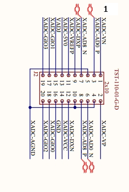
First and foremost the most important thing to specify for the XADC Header are the pinouts.

For this project we will be reading the difference between two voltage inputs within the terminal. The pins are deferentially paired and you will get the difference between Vaux8p and Vaux8n.
We will be connecting Vaux8P and Vaux8N to voltages and then Vref and all three AGNDs to ground.
**Note: After further investigation we found that you should only need both Vaux pins and the three AGND and it should work the same.

We created two voltage dividers to provide the input voltages for the Vaux8 pins. We ended up inputting about 0.75 Volts into Vaux8P and about 0.50 Volts into Vaux8N.
Below is a picture of the outputs from within the terminal:

In the terminal, Vaux8 should be reading the difference between the inputs for each Vaux8 pin, which should be around 0.25 Volts, and we are within a reasonable range of that. However, we are not sure as to why the Voltage is jumping up and then back down again for every other reading. Hopefully we will be able to modify this post once we receive an answer.
For the constraints file and helloworld.c check out our Github SienaFPGA2017 and look under Reading-Voltages-with-XADC.
UPDATE July 7, 2017
https://forum.digilentinc.com/topic/4311-zedboard-zynq-7000-xadc-header/#comment-17354
There must have been an issue with our voltage dividers causing the voltage to jump, which can be seen in the above picture. We have resolved this problem by eliminating our voltage dividers and using Waveforms 2015 instead, for our voltage source.
Set up the Waveforms window with the same selections as the image below.

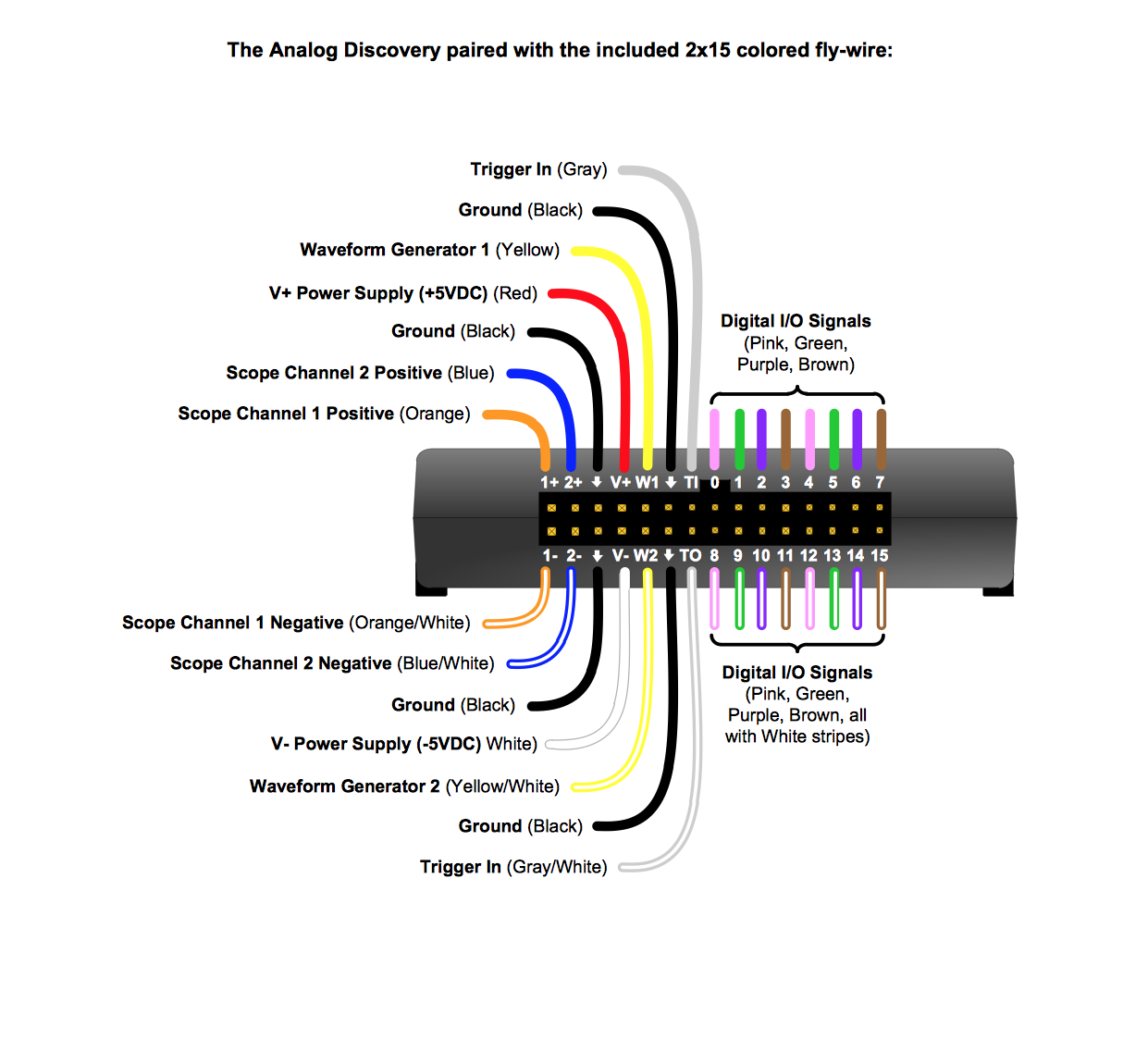
For the analog discovery legacy we will use 5 wires, two yellow and three black. From the below picture we will be placing Waveform Generator 1 (Yellow) into Vaux8P and Waveform Generator 2 (Yellow/White) into Vaux8N. As for the grounds (black) it doesn't matter which three you use you just want to connect them to the three AGNDs on the XADC Header.

Below is a picture of our new terminal readings, which are clearly more consistent and accurate than our previous attempt.

For some more information I have provided the link above to the Digilent Forums that helped to resolve this issue.

Comments
Post a Comment